Model 1095A/C Industrial GPS Clock (250 ns)
Model 1095A/C Industrial GPS Clock (250 ns)
Precision GPS timing source for industrial applications in a compact, rugged enclosure, suitable for indoor and outdoor applications.
Model 1095A/C User Manual
Download PDF(4 MB) »
Model 1095A/C Quick Setup Guide
Download PDF(684 kB) »
Model 1095A/C Data Sheet
Download PDF(352 kB) »
Model 1095A/C Data Sheet Español
Download PDF(205 kB) »
GNSS Antenna Data Sheet
Download PDF(4 MB) »
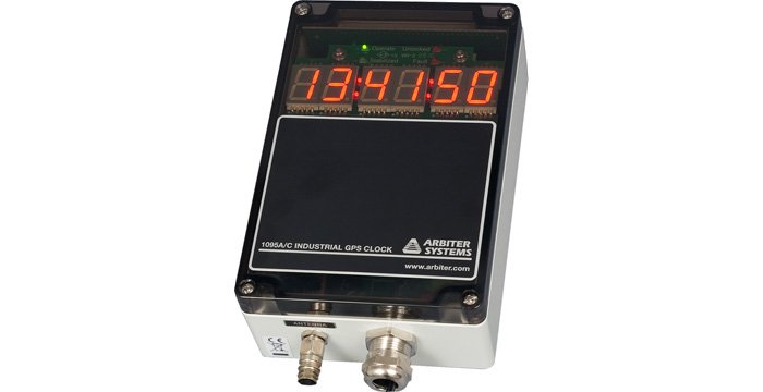
Rugged, accurate and economical, the 1095A/C GPS Industrial Clock Module from Arbiter Systems®, Inc. is the engineer's choice when flexibility, precision and physical durability are required.
The 1095A/C precision time clock is a low cost unit capable of driving common timing signals such as IRIG-B, 1PPS and RS-232 serial time codes, with < ± 100 ns typical accuracy. The compact, rugged enclosure can be mounted in multiple ways, making installation fast and secure. Ideal for outdoor applications, the 1095A/C is capable of performing when other units fail, operating between - 40 °C and 85 °C. Four configurable outputs support substantial drive capability, allowing a single unit to drive multiple loads in parallel.
The 1095A/C maintains the real-time clock, almanac and ephemeris data powered by a back up battery in the case of power loss, reconnecting to the satellite signal in as little as 15 seconds. The built in Event Capture function means the unit records key events related to data received from the input options, with 100 ns resolution.
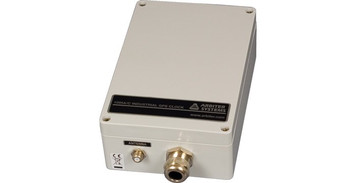
Choose between the standard internal and optional external antenna to best suit your installation environment.
Model 1095A/C supports front panel options. See photos and Key Features tab below for more information.
- Internal GPS antenna
- Rugged case for outdoor or demanding environments
- Accuracy < ± 100 ns typical; < ± 250 ns worst case
- Four terminal strip connector outputs, three high drive, one analog
- Two RS-232 ports
- One Form C (SPDT) fail-safe relay
- Battery or power source operated
Versions A/C offer various interface options (see photos):
- External GPS antenna
- 1095A utilizes an opaque cover, optionally may be ordered with a "smoked' cover
- 1095C includes a "smoked" cover with four LEDs to monitor operating status and a large seven-segment LED time display
- IEEE C37.118-2005 compliant for Synchrophasor use.
Receiver Characteristics
Timing Accuracy
| Accuracy Note | Specifications apply at the 1 PPS output, IRIG-B Level-Shift and Programmable Pulse outputs, with US Department of Defense Selective Availability (SA), as of date of publication. |
| Accuracy UTC/USNO | ± 250 ns peak; < ± 100 ns typical (SA off) |
Position Accuracy
10 meters, rms, 90 % confidence
Satellite Tracking
Twelve (12) channel, C/A code (1575.42 MHz). Receiver simultaneously tracks up to twelve satellites.
Acquisition
- 150 seconds typical, cold start
- 15 minutes, 90 % confidence, cold start
- 40 seconds, with almanac less than 1 month old
- 15 seconds, with ephemeris less than 4 hours old
I/O Configuration
Output Connectors
Four Total: three high-drive 5 Vdc (250 mA at > 4 V), one analog (4.5 Vpp), terminal strip connectors.
Output Signals
Output 1: Programmable Pulse A
Output 2: IRIG-B00x level-shift
Output 3: Programmable Pulse B
Output 4: Modulated IRIG-B
Programmable Pulse Output
Two programmable pulse outputs (5 Vdc), PPA and PPB.
Modes:
- 1 PPS
- Every 1 seconds to 60,000 seconds, starts top of the minute
- Hourly at a specified offset
- Daily at a specified time of day
- One shot at a specified time of year
- 1 PPS to 1000 PPS squarewave (PPB only)
- Aux IRIG Mode (PPB only)
Pulse duration is programmable from 0.01 seconds to 600 seconds, except in one-shot mode, where the output is Low prior to the specified time and High thereafter.
Aux IRIG Mode provides an additional unmodulated IRIG-B signal on the PPB output.
Relay Contacts
One, Form C (SPDT) fail-safe, 0.3 A at 130 Vdc; jumper selectable to Fault, Out-of-lock, Programmable Pulse A (PPA), Programmable Pulse B (PPB), Stabilized, and Event-In functions. Fail-safe means the relay indicates "fault" or "unlocked" condition with power off.
Event Inputs
One opto-isolated event capture input with 100 ns resolution, terminal strip inputs for 5 Vdc to 12 Vdc, 24 Vdc to 48 Vdc, and 120 Vdc to 240 Vdc nominal input.
Interface
Operator
| Display | 1095C Display: 6-digit LED Time of Day (20 mm) |
| Status LEDs |
|
| Setup | Via remote interface:
|
System
| RS-232 | 1200 baud to 115,200 baud; 7 or 8 data bits; 1 or 2 stop bits; even/odd/no parity (TXD, RXD, COM) |
| RS-422/485 | Transmit only, to drive multiple devices. Available Signals include: Serial Port 1, Serial Port 2, IRIG-B, PPA, PPB, and 1 PPS. |
| Broadcast modes |
|
Power Requirements
Standard
| Voltage | 9 Vdc to 30 Vdc, 3 W maximum; negative common; 3.81 mm pluggable terminal strip. |
General
Physical
I/O Port: Accepts up to a 16 conductor cable with an OD from 6 mm to 12 mm (0.24 in to 0.47 in)
| Size | 180 mm x 120 mm x 60 mm (7.1 in x 4.7 in x 2.4 in) plus cable gland |
| Weight | 1 kg (2.2 lbs), net |
| Antenna | Built-in or optional external |
| Antenna Mounting | 4 mounting feet included |
Environmental
| Temperature | Operating: - 40 °C to + 85 °C |
| Humidity | Noncondensing |
| EMC | Radiated susceptibility: passes walkie-talkie test. |
Degree of Protection
IP65 (IEC 60529), NEMA 1, 2, 4, 4x, 12, 13
Certificates and Approvals
CE mark/label and certificate
| General | |
|---|---|
| 1095Aopt02 | Smoked Enclosure Cover (1095A) |
| Antenna | |
| 1095Aopt01 | External Antenna (1095A) |
| 1095Copt01 | External Antenna (1095C) |
| Included | |
|---|---|
| AS0048900 1 | Antenna Grounding Block Kit, RoHS |
| AS0067200 | Programming Port Cable with adapter |
| AS0099200 1 | Arbiter Universal GNSS Antenna |
| HP0022601 | Sealing Cable Port (6 mm to 12 mm) |
| PD0052900 | Quick Setup Guide (1095) |
| Available | |
| AP0003400 2 | BNC (Male) Breakout to 100 mm Wires |
| AP0007700 | Modular DB-9 to RJ-11 Adapter, Preconfigured |
| AP0008900 3 | BNC (Female) Breakout to 100 mm Wires |
| AP0013100 | Wall-mount Power Supply: 110 Vac to 120 Vac, 50 Hz to 60 Hz; 9 Vdc, 0.66 A |
| AP0013200 4 | Power Supply: 100 Vac to 240 Vac, 50Hz to 60 Hz, IEC-320; 9 Vdc, 1 A |
| AP0014900 5 | BNC (Female) Breakout to Screw Terminal |
| AP0015000 6 | BNC (Male) Breakout to Screw Terminal |
| AS0044600 | Antenna Mounting Kit |
| AS0093700 | Model 1095A/C DIN Rail Mounting Assembly |
| AS0094400 7 | Power Supply 18-72 Vdc; 12 Vdc, 0.833 A |
| AS0094402 8 | Power Supply 18-72 Vdc; 12 Vdc, 0.833 A, with DIN Rail Mounting |
| AS0094500 | GNSS Surge Arrester |
| AS0096400 | Operation Manual (1095) |
| AS0096800 9 | Power Supply 85-264 Vac RMS or 110-370 Vdc; 12 Vdc, 0.9 A |
| AS0112400 | Wall-mount Power Supply: 120 Vac, 60 Hz; 12 Vdc, 0.8 A |
| CA0021302 10 | 2 m (6 ft) RG-6 Antenna Cable, RoHS |
| CA0021306 11 | 6 m (20 ft) RG-6 Antenna Cable, RoHS |
| CA0021315 10 | 15 m (50 ft) RG-6 Antenna Cable, RoHS |
| CA0021330 10 | 30 m (100 ft) RG-6 Antenna Cable, RoHS |
| CA0021338 10 | 38 m (125 ft) RG-6 Antenna Cable, RoHS |
| CA0021345 10 | 45 m (150 ft) RG-6 Antenna Cable, RoHS |
| CA0021350 10 | 50 m (164 ft) RG-6 Antenna Cable, RoHS |
| CA0021360 10 | 60 m (200 ft) RG-6 Antenna Cable, RoHS |
| CA0021375 10 | 75 m (250 ft) RG-6 Antenna Cable, RoHS |
| CA0023600 | RJ-11 Cable Four-Pin Crossed, 2 m (7 ft) |
| CA0031900 | 2 m (6.5 ft) 2 Wire, 22 AWG Cable, Bare to Bare |
| CA0031901 | 2 m (6.5 ft) 2 Wire, 22 AWG Cable, Bare to Spade |
| CA0031902 | 2 m (6.5 ft) 2 Wire, 22 AWG Cable, Bare to 3.5 mm Male Plug |
| CA0031903 | 2 m (6.5 ft) 2 Wire, 22 AWG Cable, Spade to 3.5 mm Male Plug |
| CA0032000 | 2 m (6.5 ft) 3 Wire, 22 AWG Cable, Bare to Spade |
| CA0032001 | 2 m (6.5 ft) 3 Wire, 22 AWG Cable, Spade to Spade |
| CN0027700 | Type F, Male, RG-6 Antenna Cable Crimp-on Connector, non-RoHS |
| CN0027800 | Type F, Male, RG-11 Antenna Cable Crimp-on Connector, non-RoHS |
| CN0050700 | Type F, Male, RG-6 Antenna Cable Compression Connector, RoHS |
| CN0050800 12 | Type F, Male, RG-6 Plenum Rated Antenna Cable Compression Connector, RoHS |
| CN0051300 | Type F, Male, RG-11 Antenna Cable Compression Connector, RoHS |
| HP0022602 | Sealing Cable Port: (5 mm to 9 mm) |
| TF0006000 | Type F, RG-11 Antenna Cable Crimp Tool |
| TF0006400 | Type F, RG-6 Antenna Cable Crimp Tool |
| TF0013200 | Antenna Cable Stripping Tool, RG-6 |
| TF0013300 | Antenna Cable Stripping Tool, RG-11 |
| TF0024000 | Type F, RG-6 Antenna Cable Compression Tool |
| TF0024100 | Type F, RG-11 Antenna Cable Compression Tool |
| WC0004900 10 | 300 m (1000 ft) Roll RG-11 Cable, RoHS |
| WC0005000 10 | 300 m (1000 ft) Roll RG-6 Cable, RoHS |
| WC0005200 13 | 300 m (1000 ft) Roll RG-6 Plenum Rated Cable, RoHS |
| WC0006400 | 22-12P STR TNC 150 V 80 C Unshielded Cable |
1 Included only when Opt01 is ordered
2 Converts female BNC-terminated coaxial cable to pair of wires.
3 Converts male BNC-terminated coaxial cable to pair of wires.
4 Requires additional cabling for a complete solution. Recommendation: P01 - P10.
5 Converts pair of wires to female BNC.
6 Converts pair of wires to male BNC.
7 DIN Rail Mounting Kit Not Available. Requires additional cabling for a complete solution. Recommendation: CA0031901 and CA0031902.
8 DIN Rail Mounting Kit Available. Requires additional cabling for a complete solution. Recommendation: CA0031901 and CA0031902.
9 DIN Rail Mounting Kit Available. Requires additional cabling for a complete solution. Recommendation: CA0032001 and CA0031903.
10 Stocked length. Custom lengths available from 0.3 m (1 ft) to 300 m (1000 ft). Contact factory.
11 Included only when Opt01 is ordered. Default:Stocked length. Custom lengths available from 0.3 m (1 ft) to 300 m (1000 ft). Contact factory.
12 Indoor use only. Not weather resistant. Not UV radiation protected.
13 Stocked length. Custom lengths available from 0.3 m (1 ft) to 300 m (1000 ft). Contact factory. Indoor use only. Not weather resistant. Not UV radiation protected.
| Click to Download Latest Version of Software | |
|---|---|
| 1095_Utility_02Apr2010_0750 | View and modify configuration settings. |
| 1095_Utility_SHA256_02Apr2010_0750 | 1095_Utility SHA256 checksum |
| Tera Term_01Jan2010_23 | Terminal program that can capture data from Models 930A and 931A. Also, can program the Satellite Clocks via serial commands. Modern version is available from their website: https://teratermproject.github.io/index-en.html |
| Tera Term SHA256_01Jan2010_23 | Tera Term SHA256 checksum |
Software Version and Related Information
Model 1095A/C Utility Application
Using Model 1095A/C Utility Application software (1095utility_vxxxx.exe):
- The xxxx refers to the version number of the 1095A/C Utility
- Connect the 1095A/C to the computer
- Run 1095utility_vxxxx.exe
- Click the Version tab
- If the data is blank then click Unit > Read
1095 GUI Utility Software (1095_Utility)
The software interface specifically written for the Model 1095B/C.
- Allows configuration of Model 1095B/C
- Supports viewing and modification of existing configuration on Model 1095B/C from your PC.
- Saves the existing configuration file from the 1095B/C to your PC.
- Compatible with Windows 7 and 10
Windows 10
Windows 10 does not play nice with the 1095_Utility as is. The workaround:
- Download this zip file of the 1095_Utility files 1095utility_v0750.zip
- Compare the SHA256 file checksum
- Unzip the file in an executable location such as Documents
- Find/open the unzipped folder
- Double-click on the 1095.exe
- If there is only one COM port and it is not selectable from the utility then you can manually edit the 1095util.cfg file.
- Close the utility
- Open 1095util.cfg with Notepad
- Scroll toward the bottom - looking for 'port' and 'COM1' (most likely)
- Change the COM1 to the necessary port number
- Save the file
- Open the utility and the correct COM port should be listed. Change the baud as necessary from within the utility. Default is 9600,8,N,1
| Version | Rev Level | Version Notes |
|---|---|---|
| 02Apr2010 | 0.7.5.0 |
|
1095_Utility_SHA256
| Version | Rev Level | Version Notes |
|---|---|---|
| 02Apr2010 | 0.7.5.0 |
Terminal Emulation Program (Tera Term)
Free software terminal emulator (communications program) for Microsoft Windows.
- Tera Term (Pro) is a free software terminal emulator (communication program) for MS-Windows.
- Supports VT100 emulation, telnet connection, serial port connection, etc.
Tera Term SHA256
| Firmware Information (EPROM based firmware is not available for download) | |
|---|---|
| 1095_Firmware_04Mar2019 | Downloadable. Use the Utility to import file into unit. |
| 1095_Firmware_SHA256_04Mar2019 | 1095_Firmware SHA256 checksum |
Firmware Version and Related Information
Read the release notes BEFORE downloading any firmware.
- This software interface is for use only with Model 1095A/C.
- Allows user to configure the 1095A/C
- Supports reading the existing configuration from the 1095A/C to your PC.
- Saves the existing configuration file from the 1095A/C to your PC.
- Compatible with Win 98/NT/2000/XP
Firmware Uploader
- Required to upload the firmware to the Model 1094B.
- Compatible with Windows NT, 2000 and XP
How do I find my firmware revision?
Using Serial Commands:
- Start a terminal program such as TeraTem (available for download on this page)
- Configure for 9600, 8, N, 1
- Press V
- Press E
- The terminal program should show the firmware revision date in the format dd mmm yyyy.
Using the 1095GUI utility program (1095utility_vxxxx.exe):
- The xxxx refers to the version number of the 1095GUI Utility
- Connect the 1095A/C to the computer
- Run 1095GUI (1095utility_vxxxx.exe)
- Click the Version tab
- If the data is blank then click Unit > Read
Downloadable firmware upgrade (1095_Firmware)
| Version | Rev Level | Version Notes |
|---|---|---|
| 04Mar2019 | Updates are not security related.
Do NOT load older firmware to the new processor. Just don't try it. Follow the warnings of the firmware updater. Otherwise the Model 1095A/C will cease to function properly. Posted to web site: 06 March 2019. |
|
| 22May2017 | Updates are not security related.
|
|
| 03Apr2017 | Updates are not security related.
|
|
| 16Mar2017 | Updates are not security related.
|
|
| 02Nov2015 |
|
|
| 08Mar2013 |
|
|
| 12Dec2011 |
|
|
| 06Sep2011 |
|
|
| 24Feb2010 |
|
|
| 05Jan2010 |
|
|
| 01Sep2009 |
|
|
| 28Jul2009 |
|
|
| 30Jun2009 |
|
|
| 14Jan2009 |
|
1095_Firmware_SHA256
| Version | Rev Level | Version Notes |
|---|---|---|
| 04Mar2019 |
GPS Substation Clock Requirements
Download gps_substation_clock_requirements.pdf (25 kB) »
IRIG-B Time Code Accuracy, IED and System Design Issues
Download irig_accuracy_and_connection_requirements.pdf (31 kB) »
NERC PRC-002 and PRC-018 Compliance Statement
Download pd0042900a_NERC_PRC-002_PRC-018_compliance_statement.pdf (70 kB) »
Time in the Power Industry: How and Why We Use It
Download TimeInThePowerIndustry.pdf (407 kB) »
Why GPS Clocks Are Not Free
Download why_gps_clocks_arent_free.pdf (12 kB) »
App Note 101: Distributing Timing Signals in a High-EMI Environment
Download application_note_101.pdf (90 kB) »
App Note 103: Large Format Displays with Arbiter products
Download application_note_103.pdf (16 kB) »
GPS Antenna Mounting Bracket
Download antenna_mnt_bracket_brief.pdf (462 kB) »
GPS Antenna Mounting Bracket Instructions
Download pd0024700_gps_antenna_mounting_bracket.pdf (580 kB) »
GNSS Antenna Preamplifier Installation Instructions
Download pd0025300_gnss_antenna_preamplifier.pdf (3 MB) »
IRIG Standard 200-16
Download irig-b_200-16.pdf (857 kB) »
IRIG-B Specifications
Download irig_b_spec_brief.pdf (488 kB) »
Model 1095A/C DIN Rail Mounting Assembly Instructions
Download 1095_din_rail_mounting_assembly.pdf (117 kB) »
GNSS Surge Protector Installation Instructions
Download pd0045800_surge_protector_installation_instructions.pdf (110 kB) »
Reducing Overshoot and Ripple in Arbiter Products with High Drive Outputs
Download pd0046200_reducing_high_drive_overshoot.pdf (277 kB) »
Timing Signals, IRIG-B and Pulses
Download pd0043200_timing_signals_overview.pdf (197 kB) »
Catalogo de Productos de Sincronizacion y Frecuencia
Download catalogo_de_productos_de_sincronizacion_y_frecuencia.pdf (312 kB) »
Press Release: Leap Second Anomaly December 2016
Download PD0054900_LeapSecondPressRelease.pdf (70 kB) »
Antenna Cable Assemblies RoHS2 Declaration of Conformity
Download Antenna_Cable_Assemblies_RoHS2_DoC.pdf (286 kB) »