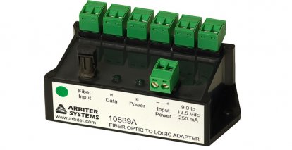
Model 10889A Fiber-Optic to Logic Adapter, 6 Output
Model 10889A Fiber-Optic to Logic Adapter, 6 Output
Converts signals recevied via optical fiber into CMOS logic levels
Model 10889A Data Sheet
Download PDF(544 kB) »
The Model 10889A Fiber-Optic to Logic Adater converts signals received via optical fiber into CMOS logic levels. The received signal is distributed to six individually-buffered outputs, each using a two-pin connector. Mating connectors are supplied with the unit.
The outputs deliver 0 volt to 5-volt logic signals, with a high output corresponding to fiber illumination. A green light-emitting diode (LED) is lighted whenever the output levels are high.
- Converts signals from optical fiber to CMOS logic level signals
- Type ST fiber optic connection.
- Up to six pluggable terminal strip outputs available
- Works with all Arbiter GPS satellite-controlled clock products
- Specified with 50/125 μm, 62.5/125 μm, 100/140 μm, and 200 μm HCS Fiber.
Ordering checklist:
- Required:
- Power Supply: Choose from the many listed under the Accessories tab.
Note: Not all power supplies have DIN Rail mounting available.
- Power Supply: Choose from the many listed under the Accessories tab.
- Optional (Must be chosen at time of order):
- DIN Rail Mounting for the 10889A module. Look on the Options tab for ordering information.
- DIN Rail Mounting for select power supplies. Look on the Accessories tab for power supply details.
I/O Configuration
Output Signals
+ 5 V CMOS signal via six, two terminal headers (mating connectors supplied).
Impedence: 10 ohms
Source/Sink Capability: ± 75 mA maximum per output, for 50 % maximum duty cycle
Input Connectors
Type ST
Input Signals
Fiber-optic signal via a 62.5/125 μm fiber, - 10 to - 24 dBm input level
Note: Also usable with 50/125 μm, 100/140 μm, and 200 μm PCS fiber
Power Requirements
Power Input
+ 9 Vdc to + 13.5 Vdc, 250 mA; input power connector, terminal block
Power Supply
A power supply is required. Choose one from the Accessories tab.
General
Physical
| Size | 102 mm x 56 mm x 42 mm (4.0 in x 2.2 in x 1.7 in), including mating connectors |
| Weight | 165 grams (5.8 oz) |
Environmental
| Temperature | Operating: - 10 °C to + 50 °C Nonoperating: - 40 °C to + 75 °C |
| General | |
|---|---|
| 10889AoptDIN | DIN Rail Clips |
| Available | |
|---|---|
| AP0003400 1 | BNC (Male) Breakout to 100 mm Wires |
| AP0008900 2 | BNC (Female) Breakout to 100 mm Wires |
| AP0013100 | Wall-mount Power Supply: 110 Vac to 120 Vac, 50 Hz to 60 Hz; 9 Vdc, 0.66 A |
| AP0013200 3 | Power Supply: 100 Vac to 240 Vac, 50Hz to 60 Hz, IEC-320; 9 Vdc, 1 A |
| AP0014900 4 | BNC (Female) Breakout to Screw Terminal |
| AP0015000 5 | BNC (Male) Breakout to Screw Terminal |
| AS0094400 6 | Power Supply 18-72 Vdc; 12 Vdc, 0.833 A |
| AS0094402 6 | Power Supply 18-72 Vdc; 12 Vdc, 0.833 A, with DIN Rail Mounting |
| AS0096800 7 | Power Supply 85-264 Vac RMS or 110-370 Vdc; 12 Vdc, 0.9 A |
| AS0106600 | DIN Rail Mounting Kit for AS0096800 |
| CA0031900 | 2 m (6.5 ft) 2 Wire, 22 AWG Cable, Bare to Bare |
| CA0031901 | 2 m (6.5 ft) 2 Wire, 22 AWG Cable, Bare to Spade |
| CA0031902 | 2 m (6.5 ft) 2 Wire, 22 AWG Cable, Bare to 3.5 mm Male Plug |
| CA0031903 | 2 m (6.5 ft) 2 Wire, 22 AWG Cable, Spade to 3.5 mm Male Plug |
| CA0032000 | 2 m (6.5 ft) 3 Wire, 22 AWG Cable, Bare to Spade |
| CA0032001 | 2 m (6.5 ft) 3 Wire, 22 AWG Cable, Spade to Spade |
1 Converts female BNC-terminated coaxial cable to pair of wires.
2 Converts male BNC-terminated coaxial cable to pair of wires.
3 Requires additional cabling for a complete solution. Recommendation: P01 - P10.
4 Converts pair of wires to female BNC.
5 Converts pair of wires to male BNC.
6 Requires additional cabling for a complete solution. Recommendation: CA0031901 and CA0031900.
7 Requires additional cabling for a complete solution. Recommendation: CA0032001 and CA0031901.
Distributing Timing Signals in a High-EMI Environment
Download application_note_101.pdf (68 kB) »

