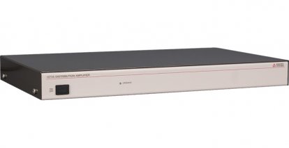
Model 1073A Distribution Amplifier
Model 1073A Distribution Amplifier
Time Code Distribution Solution - designed to buffer and distribute signals generated by other Arbiter GPS Satellite-Controlled Clocks.
Model 1073A User Manual
Download PDF(499 kB) »
Model 1073A Quick Setup Guide
Download PDF(214 kB) »
Model 1073A Data Sheet
Download PDF(798 kB) »
Model 1073A Data Sheet Español
Download PDF(284 kB) »
Looking for a time code distribution solution? Need even more outputs? Is your installation spread across a wider geographic area? Is a second clock not practical? The Model 1073A was built to address these and other challenges, while providing the flexibility to configure the device to fit specific needs.
Designed to buffer and distribute time codes and signals generated by sources such as Arbiter Systems' GNSS Synchronized Clocks, GPS Satellite Controlled Clocks, and GPS Substation Clock. Model 1073A includes three separate channels, each with four high drive outputs. Via copper or the optional fiber optic board, you can link additional facilities easily, and still get the high accuracy without adding more clocks.
Output capabilities include AC and DC coupled modes. In AC-coupled mode, the unit can receive and distribute timebase and reference frequency signals up to 10 MHz. In DC-coupled mode, Model 1073A can distribute 5 V CMOS/TTL logic-level signals such 1 PPS and unmodulated IRIG-B timecode.
Note: Because of the limiting amplifiers and frequency limit when AC-coupled, the Model 1073A is not suitable for distribution of modulated IRIG-B signals.
- Ability to extend time signals generated by Arbiter Systems' GNSS Synchronized Clocks (1201B/C, 1202B/C. . .), GPS Satellite Controlled Clocks (1088B, 1093B/C. . .), and GPS Substation Clock (1094B)
- Copper or fiber-optic cabling input support
- Time code and frequency signals support (not suitable for distribution of modulated IRIG-B signals)
I/O Configuration
Channels Three, each with four outputs
Mode:
- Independent Each channel independently driven
- Common A/B B/C outputs driven by A or B input
- Selection Internal push-on jumpers
Output Connectors
50-ohm BNC, four per channel
Fiber Optic Type ST, for 62.5/125 µm multimode fiber, optional (1073opt01)
Output Signals
Driver Each output, 74HC125 quad buffer
Coupling AC (0.1 µf capacitor) or dc (Selected by internal push-on jumpers)
Level 5 Vpp, open-circuit; 2.5 Vpp (+ 12 dBm), into 50 ohms
Impedance 50 ohms
Input Connectors
Isolated 50-ohm BNC, 1 per channel
Input Signals
DC coupled Opto-isolator (HCPL2601) in series with 562-ohm resistor
- Level 5 mA at 5 volts, nominal
- Polarity Center conductor positive
- Frequency DC to 5 MHz
AC coupled RF transformer; 50 ohms
- Level 0 to + 15 dBm (0.6 Vpp to 3.6 Vpp)
- Frequency 100 kHz - 10 MHz
Selection Internal push-on jumpers
Isolation 2000 Vrms, minimum, to common
Interface
Operator
| Status LEDs | Power On (green) |
Power Requirements
Standard
| Voltage | (Option 07) 85 Vac to 264 Vac, 47 Hz to 440 Hz, 20 VA maximum or 110 Vdc to 370 Vdc, 15 W maximum |
| Inlet | (Option 07) IEC-320 with fuse and mating cordset. Specify option P01 - P10 Available cordset plug style and specifications are described in the Options and Accessories section. |
General
Physical
| Size | 1 RU rack mount or tabletop; 260 mm deep FMS. Rack mounts included. |
| Weight | 2 kg (4.5 lbs), net |
Environmental
| Temperature | Operating: 0 °C to + 50 °C (- 20 °C to + 70 °C typical) |
| Humidity | Noncondensing |
| EMC | Radiated susceptibility: passes walkie-talkie test Conducted emissions: power supply complies with FCC 20780, Class A and VDE 0871/6.78 Class A Surge withstand capability (SWC), power inlet: designed to meet ANSI/IEEE C37.90-1 and IEC 801-4 |
Certificates and Approvals
CE mark/label and certificate
| I/O | |
|---|---|
| 1073opt01 | Fiber-Optic Input |
| General | |
| 1073opt04 | On/Off Switch (1084B/1093B) |
| Power | |
| 1073opt07 | IEC-320 Power Inlet 85 Vac to 264 Vac RMS, 110 Vdc to 370 Vdc |
| 1073opt08 | 10 Vdc to 60 Vdc Terminal Power Strip and Surge Withstand |
| 1073opt10 | 85 Vac to 250 Vac RMS, 110 Vdc to 350 Vdc Terminal Power Strip and Surge Withstand |
| Included | |
|---|---|
| AS0028200 | 19 Inch Rack Mount Kit |
| P01 - P10 1 | Country specific power cord with straight female end |
| PD0053200 | Quick Setup Guide (1073) |
| Available | |
| AP0003400 2 | BNC (Male) Breakout to 100 mm Wires |
| AP0008900 3 | BNC (Female) Breakout to 100 mm Wires |
| AP0014900 4 | BNC (Female) Breakout to Screw Terminal |
| AP0015000 5 | BNC (Male) Breakout to Screw Terminal |
| AS0045800 | Operation Manual (1073A) |
| AS0056600 | 24 Inch Rack Mount Kit |
| CA0026000 6 | Power Cord IEC-320 to Bare Leads |
1 Only applies if Power Option 07 is ordered
2 Converts female BNC-terminated coaxial cable to pair of wires.
3 Converts male BNC-terminated coaxial cable to pair of wires.
4 Converts pair of wires to female BNC.
5 Converts pair of wires to male BNC.
6 Used with Option 07.
No additional software information is available for this product
No additional firmware information is available for this product
App Note 101: Distributing Timing Signals in a High-EMI Environment
Download application_note_101.pdf (90 kB) »
Timing Signals, IRIG-B and Pulses
Download pd0043200_timing_signals_overview.pdf (197 kB) »

